
It is always a treat to run across a website with a ton of information.
We have all the parts you need for your kz400 rebuild Just shoot us an email with the parts you need.
shop@speedmotoco.com
https://www.speedmotoco.com/SearchResults.asp?Search=kz400
KZ 400 B Engine rebuild
by Rod Gibson
This article is re-posted
with the courtesy of
Rod Gibson
From "Dr Rod's" Bikerworld , and editor of The Classic Motorcycle Mechanichs
Stripping down the engine

1. It was obvious this engine had covered some considerable mileage. It was deeply caked in grease and road muck, and my first task was to clean as much of the crud off as possible. An hour spent with an assortment of paintbrushes, old toothbrushes and paraffin began to reveal a recogniseable engine, and the stripdown could begin.

2. Kawasaki's Z440 engine follows conventional Japanese twin cylinder engine design in that it has a 360 degree firing angle (both pistons rising and falling together) and a single overhead camshaft driven by a central chain. Less conventionally it has a chain primary drive, which in effect means the engine runs "backwards", and a system of balance weights in the crankcase designed to counter the effects of vibration. I started the strip by removing this breather cover from the top of the rocker box.

3. Next the rocker box itself can be removed. Slackening the bolts in sequence allows the cover to be lifted off the top of the engine, revealing the camshaft and tops of the four valves. I took the precaution of loosening the rocker inspection caps first, as this will be difficult later.
4. The rocker box carries the four rocker arms on their captive pivot pins. I'll strip these for a closer examination later, but most wear usually takes place on the cam followers as they skid over the cam lobes. There's no apparent signs of scuffing on these, which bodes well for the rest of the engine. Note the tacho drive gear offset to the right.

5. Before I can remove the camshaft I have to release the camchain tensioner to get lots of slack in the chain. Because the Z440 engine runs "backwards", (i.e. the crank rotates the opposite way to the back wheel), the tensioner is mounted on the front of the engine block instead of the usual place on the back. With the cap removed the tensioner unscrews from the block and I can withdraw the plunger and spring.

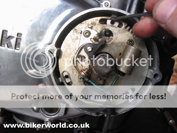
6. To unscrew the two bolts holding the cam sprocket to the camshaft I'll need to rotate the engine. A dummy nut mounted on the auto advance usually does the job, so at this stage I opt to remove the contact breaker backplate. The Z440 uses a "wasted spark" ignition system, so only has one set of points. Marking the backplate first to aid re-assembly, I can now remove the three retaining screws and lift the backplate off.

7. A good heave with a spanner on the dummy nut suceeds only in shearing off the auto advance drive pin; this engine is well and truly seized. I decide to fill the cylinders with penetrating oil and leave it for a few hours before proceeding. Hopefully I'll be able to re-claim the drive pin later on.

8. After a suitable pause to let the penetrating oil work, I continue by removing the generator cover. This carries the alternator stator, and I wrap it in rags to avoid any damage to the windings before laying it aside. Now I have access to the rotor bolt I can try to turn the engine with a socket on a long extension bar. Fortunately it frees off without too much drama and the engine turns over for the first time. It still feels a little rough though, and I'll reserve judgement on the state of the engine internals until the barrels are off.
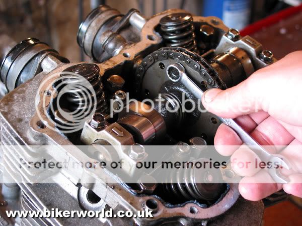
9. Returning to the top end I can now slacken and remove the two short 6mm bolts which hold the cam sprocket onto the camshaft. Before removing these completely I've taken the precaution of making a sketch of the timing marks on the sprocket. I have a workshop manual on the shelf, but I always like to check timing marks before stripping an engine down just to make sure it goes back together the same way.

10. With the two bolts removed the cam sprocket can be dropped sideways off its mounting flange, leaving plenty room to maneouvre the camchain free. Unbolting and removing the three cam caps means I can now lift the camshaft out. The three cam caps are arrowed and must be replaced in the same positions, so I pop them back onto the head and wind their mounting bolts in by hand to make sure nothing gets lost or misplaced later. Each cap bolt has a dowel, make sure you don't lose them down the camchain tunnel when lifting the caps off.

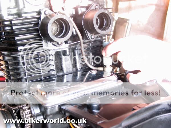
11. Before the head can be removed this external oil feed pipe has to be removed. Some Japanese engine designers chose to route the camshaft oil feeds up through the head bolts and through drillings in the cylinder head. Kawasaki, like Yamaha, tended to favour an external pipe like this one on their twins. The oil feed pipe mounts onto the oil pressure switch at the rear of the crankcase, which can also be removed at this stage.

12. Now I can remove the eight main head nuts and lift off the cylinder head. The head nuts should be slackened off in sequence working diagonally, and Kawasaki have helpfully cast in numbers alongside each nut to indicate the correct sequence. A sharp crack with a rubber mallet breaks the head gasket seal, and I can lift the head off and put it to one side for attention later.
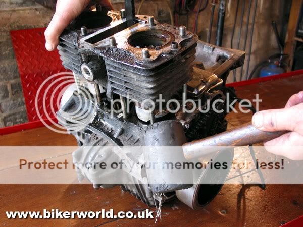
13. The barrels should now slide upwards off the pistons, but are reluctant on this engine. Though I've succeeded in freeing it off, the piston rings have obviously corroded into the bores. At this stage I'm beginning to think we will have to re-bore the engine to make it serviceable, but careful work might yet mean I can salvage the bores and get away with just new rings. Gentle tapping with a rubber mallet eases the barrels slowly off the pistons until I can eventually lift them clear.
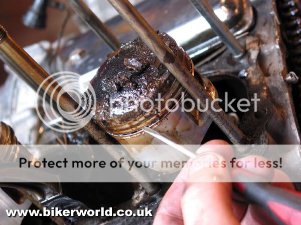
14. With the barrels off the extent of the damage to the pistons and rings is revealed. The rings have started to rust into the bores, almost undoubtedly because the engine had been left with its spark plugs removed, allowing in moisture. The rings have stuck into the piston grooves, and I'll spend some time with them later once I've evaluated the condition of the bores. The crud on top of the piston crowns would appear to be heavy carbon deposits, suggesting the engine was burning oil heavily before it was taken out of service. All worthy of note at this stage.

15. Removing the pistons is straight forward enough. With the outer circlip removed each gudgeon pin can be tapped through the small end until the piston can be lifted clear. As always I've taken the precaution of marking the inside of each piston skirt with a reference mark, so if I do decide to re-use the pistons they can go back on the same rods. And I've also thrown away the old circlips to avoid any temptation to re-use them.

16. Next, the starter motor. Two small bolts hold the rectangular chrome cover in place. With these removed the starter itself can be released by removing two 6mm bolts which secure it onto the crankcase top. The motor drives the starter clutch via an endless single row chain. The chain drive sprocket simply slides off the splined shaft, and I can pull the starter motor body sideways and upwards to release it. Finally I can hook the drive chain off over the generator rotor and store it away.

17. Turning to the right side of the engine I can now remove the outer engine cover to reveal the clutch and primary drive. I always use an impact driver to remove cross head casing screws, especially when they haven't been disturbed for some time. Some of these screws showed evidence of previous damage, but I'll be replacing them with Allen screws on the rebuild anyway.

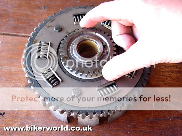
18. The primary chain is a heavy duty Hy-Vo item, and is endless. To remove it the primary drive sprocket and clutch basket must be removed together. After removing the clutch pressure plate and friction plates I can take off this circlip which retains the clutch inner drum onto the gearbox input shaft. A similar circlip holds the primary drive gear onto the end of the crankshaft. Most designs use large nuts and locktabs, these circlips make this part of the job much easier.

19. Now I can lift the primary drive away as an assembly. The primary chain wears very slowly and has no tensioner as such, but runs over two nylon slipper blades bolted into the outer cover. Chains of this type can be very expensive to replace, and I'm hoping it's still within service limits.

20. Behind the clutch are the oil pump, the gear selector mechanism and kickstarter, all of which must be removed before splitting the crankcases. The oil pump is retained with four cross head screws which free off easily after a crack with the impact driver. This oil pump has the word "ASCO" stamped into its drive gear, which I don't recall ever seeing on a bike before. I wonder if this could be an aftermarket oil pump of some kind, and would be interested to know it's origin.

21. Next, the gear selector. A small catch plate, retained by two screws, holds the selector shaft in position. With this catch plate removed the selector claws can be unhooked from the end of the drum and the whole shaft slid sideways out of the engine and set aside. This is the part you'd be replacing if you had damage to the splines retaining the gear lever. Finally the kickstarter mechanism can be turned and lifted clear after removal of its retaining circlip.

22. Turning the engine over, I next remove this small cast housing which conceals a gauze strainer for the engine oil. This gauze strainer is frequently overlooked, but should ideally be removed and cleaned at every major service. Encouragingly, this one shows little signs of debris in the engine oil despite the fact that it obviously hasn't been disturbed for some considerable time.

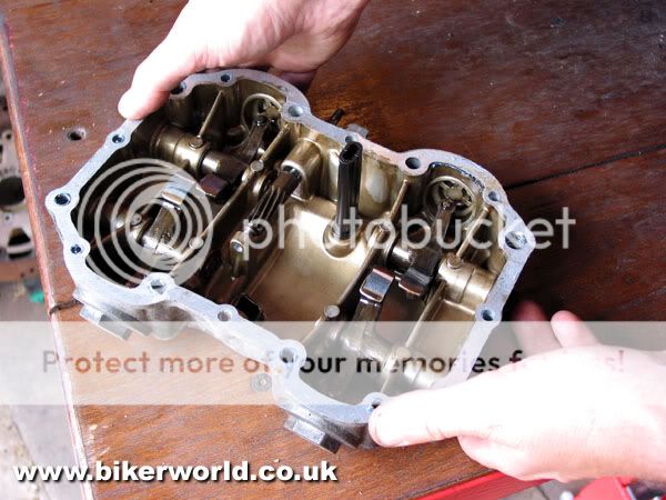
23. Now I can split the crankcases. A number of bolts hold the two halves together, from both above and below, some of which can be easy to miss under caked-on grease. With all the bolts removed the lower crankcase should seperate from the upper with a smart tap from the rubber mallet. Lifting the lower half clear reveals the two gearbox shafts and the crankshaft. It also reveals the alloy casting around the crank which carries the balancer weights.

24. Before removing the balancer weight housing I'm checking the timing marks on the weights themselves. These weights counterbalance the mass of the pistons, and will have to be correctly timed on re-assembly. The weights are driven by a single row chain off the crankshaft, also a candidate for wear at high mileages. Interestingly, with the front bobweight correctly lined up to its timing mark the rear bobweight looks slightly out, which may indicate a heavily worn balancer chain.
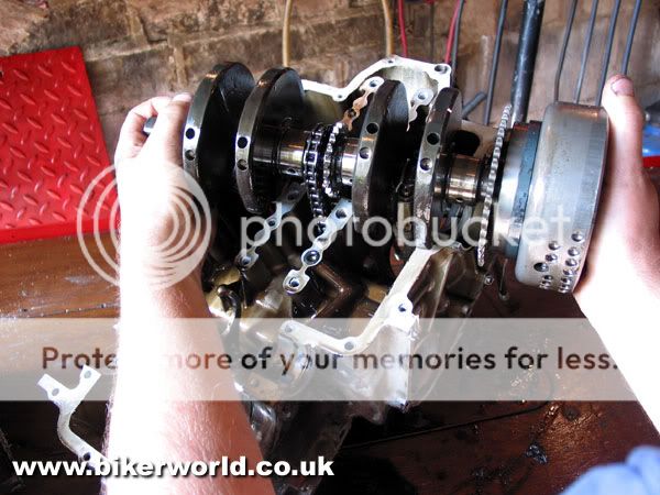
25. The crank itself runs in four shell type main bearings, the two outers sandwiched between the crankcase halves and the inners located into the balancer mounting. With the balancer mounting finally removed I can lift out the crank. At this stage the generator rotor is still bolted onto the crankshaft. I didn't have a satisfactory way of locking the engine to undo the bolt, so will clamp the crank into a vice to remove it later. The rotor could be left in place, but has to be removed to get access to the starter clutch, which I will need to check for wear.
And that's it for now. Next I need to sort through the pile of bits on the bench and carefully check everything for wear and damage before taking some decisions about how much we have to spend to make the engine serviceable. And decide who pays for the parts....
Sorting out the bits
Last update I stripped Psycho's Kawasaki 440 twin engine into it's component parts, now it's time to take a good look around the bits to see what needs to be replaced for the rebuild. Ringing Z Power for some advice about gaskets and parts availability gave me something of a surprise, as they told me the engine number I'd quoted was for an old Z400 twin, rather than a 440. Rather belatedly I scrubbed the old grease off the from the front of the cylinder barrel to reveal the capacity cast on by the manufacturer - 398cc! A good job I discovered that before ordering any parts as there are many minor but important differences between Kawasaki's early Z400 twin and the later 440 development.

1. I was hoping to avoid running up too much of a bill for Psycho, but the state of the left hand cylinder bore suggested that he was going to have to spend some money. The engine had been left with its plugs out, moisture had penetrated the cylinder and the rings had rusted badly into the bore itself. Enquiries indicated that new, genuine pistons would be expensive, so I rang Steve who immediately set about hunting down some serviceable second hand barrels, or at least some good oversize pistons we could use for a re-bore.

2. Corrosion had also begun to affect the valves, though when I removed them from the head and cleaned them up with a rotary wire brush I was pleased to see that they were still going to be useable. However the valve seats were very badly pitted and some specialist work was obviously going to be required. I took the head and valves off to Paul Coward at Bikerworld to see what could be done.
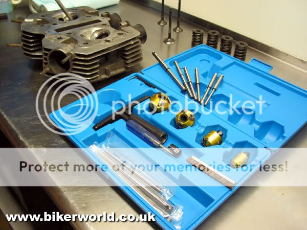
3. Paul took a good look at the valve seats before deciding that they were beyond simply lapping in with grinding paste, and would have to be re-cut. This is quite a skilled operation and requires special tools. Fortunately Paul had just received a new set of valve seat re-cutting tools from Sykes-Pickavant, and was keen to try them out on the little Kawasaki's cylinder head. The set comprises a selection of cutting heads to suit the range of valve head diameters found on common bike engines, along with an assortment of pilot bars which have to fit accurately into the valve guide to locate the cutting head.

4. The first step in the cutting operation is to mark around the valve seat with engineers blue. This will make it easy to see the pits on the valve seat when the cutting operation starts.

5. This is the cutting head itself. Cutting heads are available for different angles of valve seat, this one cuts at 45 degrees which is the usual angle for most road bikes. However on racing engines, or where some gas flow work has been carried out on the head, the seats will frequently be cut at three different angles to produce a nice, narrow sealing face and provide a smoother radius to aid gas flow. Paul explained just enough gas flow theory to me to convince me that this was highly specialist stuff, and best left to an expert like him.
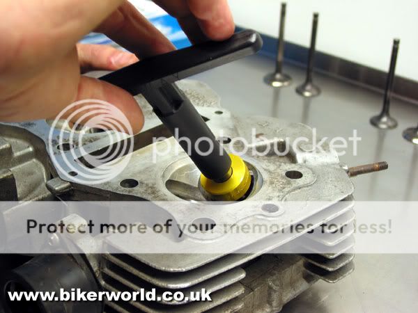
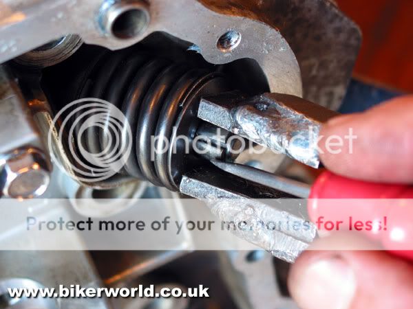
6. With the correct size pilot bar mounted into the valve guide, the cutting head slides into place and Paul gently turns it against the seat to skim off a little metal. The skill is to take off just enough metal to remove the pitting without cutting too deep. If the seats are overcut the valves will sit too deep in the head, a condition known as "pocketing". Taking of too much metal can also make the valve seats too wide.

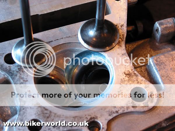
7. After skimming a little of the seat, Paul removes the cutter to check progress. You can clearly see the new metal beginning to show at the top left.

8. Of course with seats as bad as these it's inevitable that the valves will have suffered too. Close examination shows how the valves have worn into ridges, which will need to be carefully skimmed off in a lathe before they can be lapped in correctly to the re-cut seats. All this removal of metal will have an effect on how deep the valves sit into the head on re-assembly, and be very careful if undertaking this kind of work on DOHC engines as you can inadvertently go beyond the range of available shims for the valve clearances. This could make valve replacement the best option in some cases, but our Z400 uses screw and locknut tappet adjusters and shouldn't prove troublesome to set up later.
9. After some time and care Paul has successfully re-cut and lapped in all the valves and seats. Thank goodness this engine has only four valves, the thought of carrying out a similar process on a Honda CBX1000 isn't a pleasant one!
10. Finally I can re-fit the valves back into the cylinder head, having first fitted a new set of oil seals over the guides. As usual my old valve spring compressor proves invaluable. With the spring compressed I can pop the split cotters back onto each valve stem to hold everything in place, a blob of grease on the stem stops them falling out while I unwind the compressor.
11. Turning attention now to the rest of the engine I've carefully checked the bearing journals on the camshaft before using a micrometer to check the journals for wear. It's worth measuring at several places around each journal as this will reveal any ovality, but problems with the cam bearings will usually be pretty obvious with scoring present on the camshaft and cylinder head.

12. Similar measurements will reveal any wear on the big end and main bearing journals, and close visual inspection will show up any scoring here. The Kawasaki uses plain bearings as opposed to rollers, which means that some re-conditioning can theoretically be carried out if the journals have sustained any damage. However re-grinding is not usually an option as Kawasaki do not supply oversize shell bearings, and specialist attention would be required to build up worn journals and re-grind them back to standard. It's also worth checking the balancer chain drive teeth in the crank centre, early Z400s could strip teeth from here and render the balancer unserviceable, making the bike unrideable.

13. The main bearing shells themselves are a press fit into the crankcase half, and can be popped out with a small screwdriver. Although Kawasaki do not supply oversize shells they do offer three "standard" sizes, which are graded to match the journal. These grades are sometimes identified by coloured spots of paint, which can lead to some confusion when ordering replacements. The factory manual has a chart to help identify the correct shells once the dimensions are known, but if in doubt a specialist like Z Power can offer help over the phone.

14. As I'd hoped, the journals all seem fine in this case, but the shells themselves are showing their age. The old shell (right) shows clear signs of pitting compared to the new one (left). This will be worse on an engine which has not received regular oil changes throughout it's life. In any case, I'd always replace both big-end and main bearing shells as part of a full engine re-build as a matter of course.

15. The big-end shells pop out of the con rods in exactly the same way, and their replacements can be eased home by hand. It's most important that the con rod caps go back on the correct rods, and that each rod goes back on the correct journal. If in doubt I always label the rods and caps with a marker pen before disassembly, but the manufacturer should have already marked them at the factory.
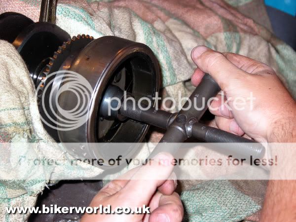
16. It is not actually necessary to remove the generator rotor from one of these engines in order to split the crankcases, but before i rebuild the engine I want to make sure the starter motor clutch is in good working order. As this is mounted behind the rotor I'll have to remove it now. With the crank carefully held between thick rags in my bench vice I can remove the centre bolt and use this useful Honda puller to pull the rotor from it's taper. Remember, though, that due to the Z400's "reversed" crank rotation, the centre bolt has a left handed thread.
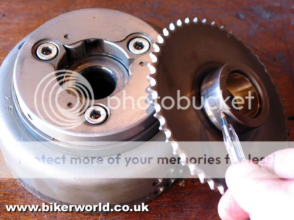
17. Now I can simply lift the starter drive wheel out of the starter clutch housing. The drive boss (indicated) can begin to develop flats after high mileages, which can cause the starter clutch to slip under load. This one does show signs of wear, but as Steve's budget is beginning to feel strained we opt to leave it. The bike does have a kickstarter after all! Note the three allen head screws which hold the starter clutch onto the back of the rotor. The old Z750 twin was notorious for writing off rotors when these screws would work loose in service. If in doubt, slot the threaded end of each bolt with a hacksaw and then spread it out to lock it into it's thread after re-tightening. Use plenty of Loctite too.

18. The Z400 has a primary chain, a camchain and a balancer chain. Rather too many internal chains for my liking, and none of them cheap to replace. The primary chain in particular is hideously expensive, but fortunately also fairly sturdy. Careful measurement of a length of the camchain here confirms my preference to fit a new one, and the balancer chain is right on the service limit too.

19. Fitting a new balancer chain involves removing the two bobweights from their mountings and looping the chain around them. I've also taken the precaution of replacing the rubber faced slipper blade mounted up inside the housing.

20. The usual routine checks for wear or damage show no signs of any problems with the gears and shafts and the sliding dogs look perfectly fine too. Always worth checking while the engine's apart though!

21. Again I check the selector forks for any signs of wear or damage. Bent selector forks will frequently show signs of heat discolouration as well as signs of scuffing on the tips, here.
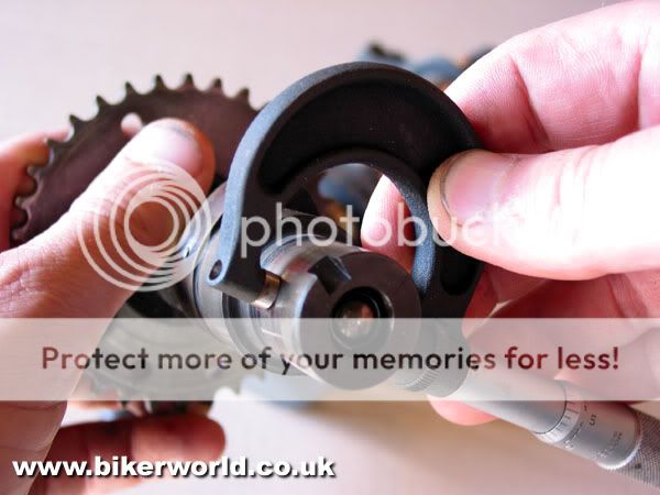
22. Still on the transmission, don't forget to check the rear of the clutch basket for any broken springs in the shock absorber. This small drive gear is for the oil pump and, unusually, is retained with a circlip.

23. The clutch plates should also be checked for wear. These are about half worn, so to keep costs down I'll be re-using them. I've also checked each of the plain plates for any signs of bucking by laying it on a piece of plate glass from an old record turntable. Unless they are perfectly flat the clutch will be difficult to adjust, and could exhibit symptoms of both slip and drag.

24. Hmm, I don't like the look of this. Something has obviously gone around inside the oil pump at some stage in the engine's life and scored the faceplate. This could reduce the running oil pressure and, mindful of the new bearing shells I'm fitting to the engine, I'll be looking for a better condition second-hand pump to fit on the rebuild.
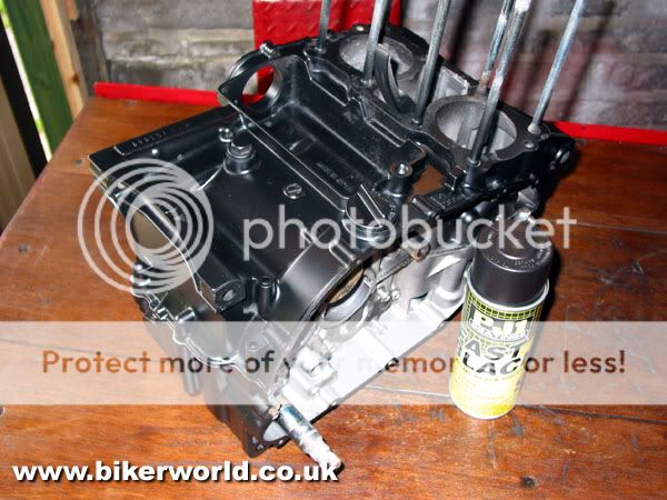
25. Finally, to make the rebuilt engine look as presentable as it deserves I've opted to give the crankcases a coat of high-temp satin black paint after thorough degreasing and cleaning in the dishwasher. Not original I know, but as the engine is to be used for a project it doesn't have to look as it did when it left the factory. Half an hour with some Solvol Autosol on the engine covers and a set of stainless screws and it should look quite presentable.
Unfortunately another phone call to Psycho reveals that good replacement pistons are proving elusive, and we're hoping something turns up in time to get the motor re-built next month. Otherwise it could be an exercise in breaking the bank! Let's hope not....
Thanks to Phil and Dave at Z Power (01942 262864) for parts and advice, Paul Coward at Bikerworld (01422 844681) for specialist cylinder head work and Sykes-Pickavant for the valve seat cutters.
Rebuilding the engine
Last update was left as a bit of cliff-hanger when we discovered how much it would cost to re-bore Psycho's Kawasaki Z400 twin engine with new genuine pistons. Apparently after market piston kits are not readily available for this model, and the price of new genuine parts would far exceed the price of simply replacing the engine with another one. So it was that Psycho went in search of second hand barrels and pistons with rather mixed results....

1. While the search for serviceable pistons continues I've made a start by beginning to rebuild the bottom half of the engine. With new big-end shells fitted to the rods and the journals copiously oiled I can re-assemble the big ends. I've added a spot of threadlock to the big end bolts before carefully torqueing up the bolts. It's not essential to re-fit the rods on their original journals and the same way round, but it's good workshop practise and I've been most careful to make sure everything is re-fitted in it's original place.

2. I'm also replacing the main bearing shells, so I've pressed them into place in the top crankcase half and oiled them with fresh engine oil before carefully lowering the crankshaft into position. The new camchain is also in position on the crankshaft. Incidentally if only replacing the camchain on one of these engines it is possible to remove the camshaft, then turn the engine over, remove the bottom crankcase half and split the big end caps. This lets you lift out the crankshaft without disturbing the head, barrels and pistons.

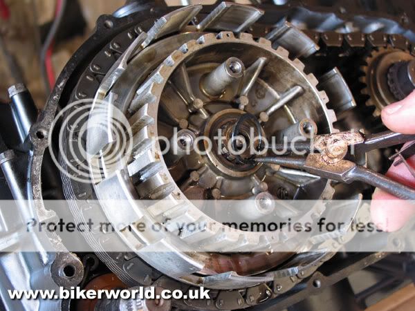
3. The centre main bearing shells fit into the balancer assembly, which needs to be fitted before the crankcase can be re-joined. As the balancer is lowered into position it's drive chain engages with the crank sprocket, and the balance weights must be timed correctly at this stage. To make sure I've got it right I've temporarily fitted the clutch case and auto-advance unit, which allows me to line up the "T" timing mark for top dead centre. The two alignment marks on the bobweights (here picked out in white paint) should now line up to their index marks. These don't look quite right to me, and refuse to line up accurately. A quick call to Phil at Z Power confirms that they are in fact correctly aligned, and the build can proceed.

4. Next the two gearbox shafts can be fitted into place, making sure the selector forks engage correctly into the grooves on the matching gears. The gearbox bearings all locate onto circlips or dowels in the top crankcase half, and I've fitted the new clutch pushrod seal. Finally with everything correctly located and a thin smear of Hylomar applied around the jointing surface, I can lower the crankcase into position and bolt it up, pausing to make sure all the shafts rotate easily before final tightening.
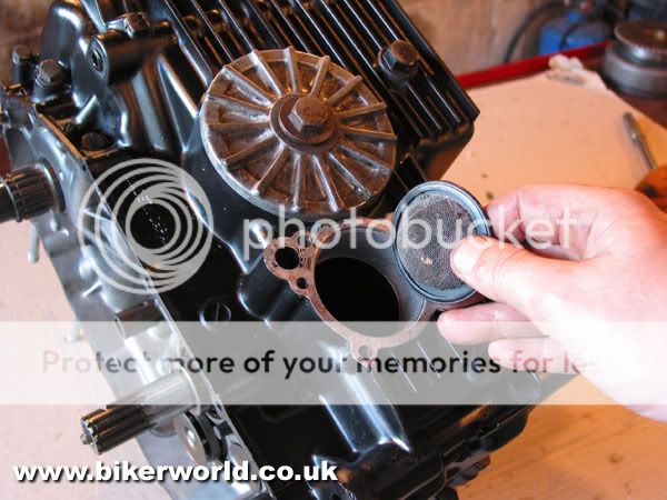
5. This is a convenient time to fit a new oil filter. I'm also re-fitting this gauze strainer into its housing before re-fitting the cover plate with a new gasket. The gauze strainer prevents foreign bodies getting into the oil pump, and it will be checked and cleaned at the first oil change after the rebuilt engine is run. Any bits of surplus gasket cement will collect here and must not be left to clog the gauze and restrict the oil flow.

6. Now to the primary drive side. First I've slotted the kickstarter assembly home and used a pair of long nosed Mole grips to tension up the return spring and hook it into place. Next, the oil pump sits on its new gasket and is retained by three cross-head screws. I always give these screws a sharp tap with an impact driver to make sure they're tight, and I've primed the pump with fresh engine oil before fitting.

7. With a new oil seal carefully pressed in to the other side of the crankcase I've greased the gearchange shaft before sliding it through the crankcase until I can engage the selector claws with the end of the selector drum. The shaft is held in position with a small catch plate fixed to the crankcase with two screws. The selector claws have a small retaining spring and a hairpin centring spring, these need to be engaged correctly as the claws are engaged.

8. Because the little Kawasaki uses an endless primary chain the clutch basket and primary drive gear must be replaced together. A washer and spacer fit over the gearbox input shaft first, then the whole primary drive assembly can be offered up and slid into place over the respective shafts.
9. Now the clutch inner drum fits onto the splined end of the input shaft. Unusually, Kawasaki's designers chose to retain both the primary drive gear and the clutch with circlips, which makes life much easier provided you own a decent set of circlip pliers.

10. Assembling the clutch is simply a matter of popping the clutch plates in, starting with a friction plate and alternating with plain plates until all are in place. The clutch pushrod slides into the centre of the input shaft, followed by a ball bearing and then the clutch lifter mushroom. A blob of Copper Slip on the lifter mushroom will prevent the "clutch shriek" common to many Kawasakis of the period. With the pressure plate fitted the springs can then be tightened down until they stop. Don't over tighten these, as it is possible to strip the threads out of the inner drum.
11. I always grease new gaskets for this kind of application, the gasket should be capable of providing an excellent seal provided the surfaces are not damaged, and grease will permit the cover to be removed at a later date without the gasket splitting. With the clutch cover re-fitted I can turn my attention to the ignition components. First the auto-advance unit pushes into place on the crank end and is retained with a single, central 8mm bolt. The unit is keyed to the crank with a tiny dowel, and will only fit in one place. Then I can fit the points backplate. I carefully punched some alignment marks before stripping the engine, so I can now refit the backplate in its original place. This should give me accurate enough ignition timing for an initial start-up, and I'll check it with a strobe later.

12. With the clutch side complete I can now move to the engine's left side. First the starter motor engages down into the crankcase and is bolted up with two M6 bolts.

13. Then I can replace the generator rotor and starter clutch assembly. Again, there's an endless chain which connects the starter drive gear to a sprocket on the end of the starter. The starter sprocket simply slides home as the generator rotor fits onto its taper. Finally a single left-hand thread bolt secures the rotor to the end of the crank. I've used a spot of blue loctite to retain it, and torqued it up tight. Then the generator cover complete with stator goes on, and the engine's sides are more or less complete.
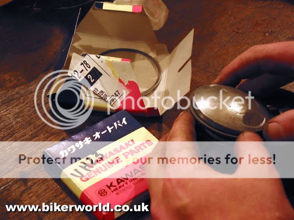
14. While I've been busy with this lot, Steve has managed to turn up trumps with a serviceable set of second-hand barrels and pistons. Unfortunately the rings that came with them were beyond further use, so Steve has invested almost £70 in a new set of standard rings. Who said parts for this engine would be cheap? After cleaning up the piston crowns I'm fitting the new rings with some care. The top ring is chrome and can go in either way up, but the second ring is cast iron and must go the right way up. A tiny letter "N" alongside the ring gap identifies the top side.

15. Fitting the pistons is easy enough, though a delicate touch is required to engage the new circlips. I've copiously oiled the small ends with clean, fresh engine oil before sliding the gudgeon pins home, and used long nosed pliers to pop the clips in. Always make certain the circlips are properly seated before moving on, a circlip which comes loose in service will cause catastrophic damage to the cylinder bore when the engine is run.

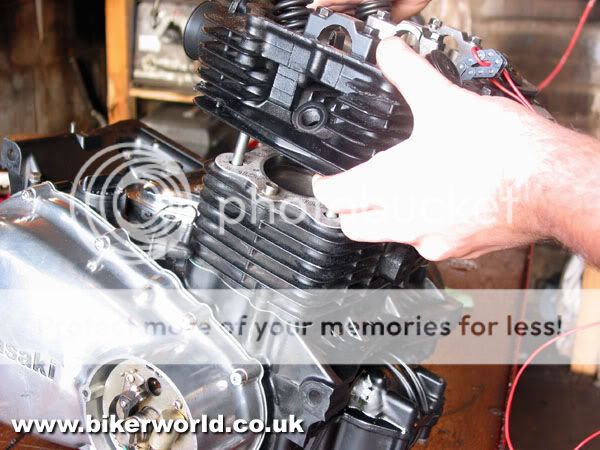
16. Before fitting the barrels I've fitted the front camchain slipper blade. Don't miss it out as you can't fit it with the barrels on. I've also tied up the camchain with a piece of electrical wire which permits me to thread it upwards through the camchain tunnel as the barrels go down. Then, with a new cylinder base gasket greased and in place, and the pistons well oiled, I can slowly lower the barrels, gently easing each piston ring into place with a small screwdriver until all are safely engaged. The barrel should then gently tap downwards onto the crankcase mouth with a rubber mallet.
17. Next a new head gasket, and the cylinder head can be placed on top of the barrels and torqued down. Some engines have small rubber "O" rings around some of the head studs to seal the camshaft oil feed, but as this engine uses an external feed there are no "O" rings to worry about. Each head nut has a copper washer to prevent oil draining down the studs from the head and leaking. Make sure the two locating dowels are in place at either side of the head before fitting, too.

18. To fit the camshaft I've removed its sprocket, then hooked it into the camchain. The camshaft drops into its freshly oiled bearings and I can feed the chain around the sprocket teeth. The trick is then to time the top sprocket to the crankshaft, which again needs to be positioned at the "T" mark for top dead centre. There's enough slack in the chain to feed the links over until the timing marks are correct.

19. With the cam sprocket sitting on its mounting flange the timing mark, here picked out with silver paint, should align with the head flange. It's then a simple matter to rotate the camshaft until the sprocket bolt holes line up and then fit the two retaining screws, again using a spot of threadlock. And if you were worrying about getting the timing 180 degrees out, forget it. The Z400's wasted spark ignition system means both cylinders fire together, on both compression and exhaust strokes.
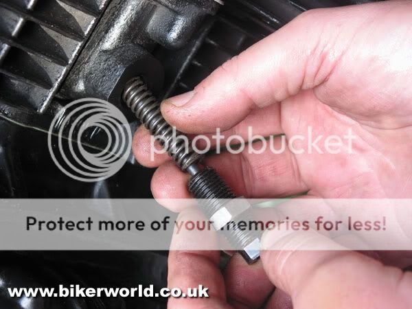
20. Now, the camchain tensioner. This is a manual tensioner comprising a springloaded plunger in an adjustable housing. With the housing screwed into the cylinder barrel until the end of the plunger is flush with the end of the housing, chain tension should be correct. And because the Z400 engine runs "backwards", the tensioner is found at the front of the cylinder barrel, not at the rear. With the tensioner correctly set, a large alloy cap screws over the top to seal it against the block.

21. This is as good a time as any to check the valve clearances. Because this engine has had significant work done to the valves and seats, it is almost inevitable that the clearances will settle down once the engine runs, so for the time being I'm setting all the clearances to 6 thou. They will need to be checked soon after the initial start-up, and again after the first 500 miles.
22. Last item on the top end is this external oil feed pipe for the camshaft. The oil pressure switch fits into the lower banjo and screws into the crankcase, while an upper banjo bolt secures it to the head. Make sure the copper washers are present and in good order.

23. The engine sprocket cover carries the clutch lifter assembly, so before fitting the cover I've removed the lifter to clean and re-grease it. The lifter comprises two ramps with sloping depressions and a centre bearing plate carrying three ball bearings. As one side of the ramp is rotated by the clutch cable the balls ride up the ramps and push the clutch pushrod to lift the clutch. The Kawasaki lifter is a tough design, and shows little signs of wear. After greasing it I can rebuild it into the sprocket cover, and fit the cover to the engine.

24. With the cover fitted, the clutch lifter is adjusted by winding it in until it meets the end of the pushrod, then backing off half a turn and locking with the locknut. A small rectangular alloy cover then bolts on to conceal it.
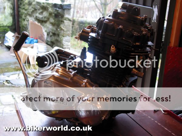
25. The finished engine ready to install in its new home. Steve managed to find a good second-hand kickstart lever, and a superb stainless screw kit from Inox Fasteners finishes off the detailing. The ever helpful John at Inox has gone to great trouble to supply top quality fasteners for what turned out to be a rather obscure engine, and I've been very impressed not only by the quality of the fasteners Inox have supplied but also the prompt service and personal interest they've taken in the project.
The plan is to use the engine to power a monowheel such as those we built in TVs "Scrapheap Challenge". With a little more time to design and plan the project it promises to be interesting, and I'm looking forward to seeing, and maybe even riding, Psycho's finished machine.
Thanks to Z Power (01942 262864) for gaskets, parts and invaluable advice and Inox Fasteners (023 8058 6805) for whom even the smallest washer is a goal worthy of pursuit.
Dr.Rod